Well settings
Well settings: 3.1.1. Settings In the Settings window, you can configure alert generation rules, virtual flow meter calculations, and units of measurement for all wells, well…
On this page
3.1.1. Settings#
In the Settings window, you can configure alert generation rules, virtual flow meter calculations, and units of measurement for all wells, well groups, or specific wells.
To open the window, at the top of the well management pane, click Settings (  ).
).
 Select image to enlarge
The window consists of several tabs located in its left part:
-
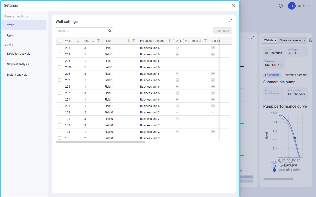
Wells: All well parameters in one place. For details, see Well Settings Window.
-
Units: Configuration of measurement units for well operation parameters. For details, see Configuring Measurement Units.
-
Deviation analysis: Parameters of alert generation based on the liquid flow rate deviations. For details, see Configuring Deviation Analysis Alerts.
-
Setpoint analysis: Parameters of alert generation based on deviations in the well operation. For details, see Configuring Setpoint Analysis Alerts.
-
Instant analysis: Parameters of alert generation based on deviations in the current or frequency of the well equipment. For details, see Configuring Instant Analysis Alerts.
3.1.1.1. Configuring General Well Settings#
On the Wells tab of the Settings window, you can configure all well parameters, both general settings and alert generation rules.
Select image to enlargeOn this tab, you can configure settings both for one well and multiple wells at the same time.
Configuring General Settings for One Well#
Configuration of a single well's settings is performed from the Well settings window that you can open in the following ways:
-
At the top of the well management pane, click Settings (
), and then, in the right part of the Wells tab, in the list of wells, hover over the desired well row and click Settings ( ). -
In the well management pane, hover over the desired well tile, and click Settings (
). Select image to enlarge
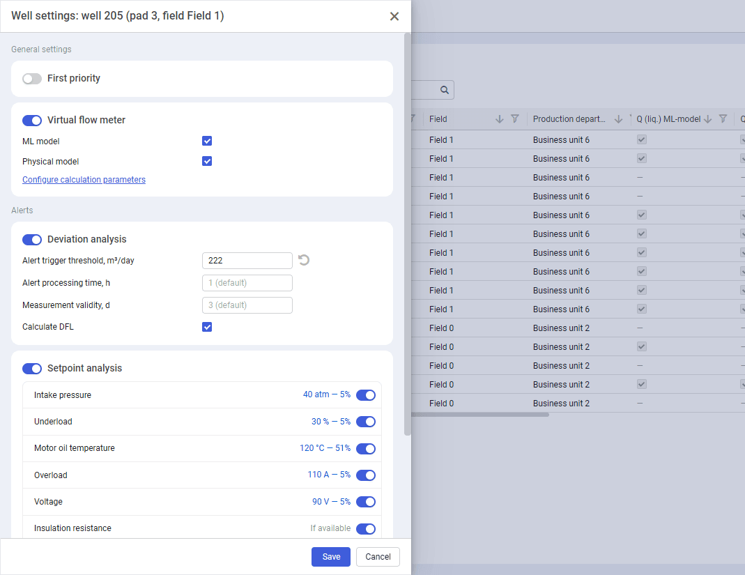
For details on the settings available in the window, see Well Settings Window.
Configuring General Settings for Multiple Wells#
To configure general settings for multiple wells, perform the following actions:
-
At the top of the well management pane, click Settings (
). The Settings window opens. -
In the right part of the Wells tab, in the table with a list of wells, select check boxes of the wells that you want to configure.
Note
You can find a well by its name. To do this, at the top of the list, in the Search field, enter the well name or a part of it.
-
(Optional) To expand the table to full screen, in the upper-right corner of the tab, click Expand (
 ).
). -
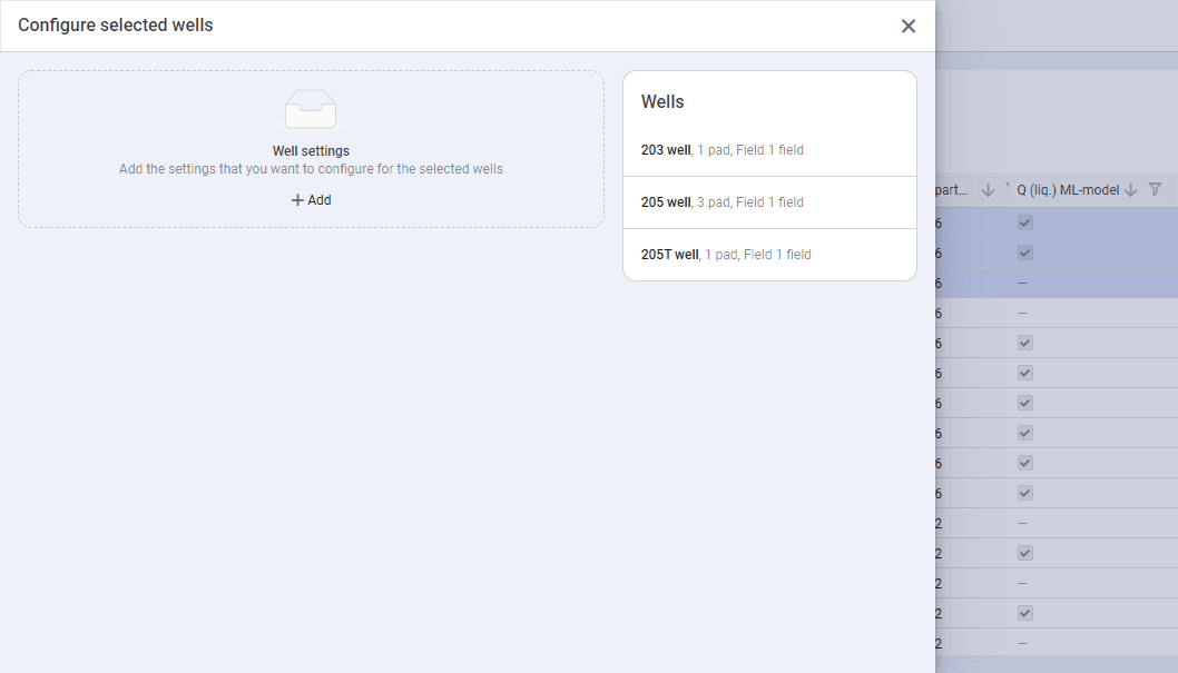
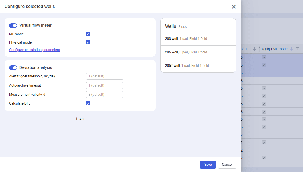
At the top of the table, click Configure. The Configure selected wells window opens with a list of selected wells in its upper- right corner.
 Select image to enlarge
Note
You can remove a well from the list of selected wells by hovering over the corresponding entry and clicking the delete icon (
 ) that appears on it.
 -
In the Well settings area at the top of the window, click Add (
 ), and select the desired settings from the drop-down list. Areas with the selected setting parameters appear.
 Select image to enlarge
 -
(Optional) To add more settings, below the most recently added setting, click Add (
), and select the desired option or options from the drop-down list.Note
You can remove an already added setting by hovering over the corresponding area and clicking the delete icon (
) that appears on hovering. -
Configure the selected settings. Available parameters are the same as those in the well settings window. For details, see Well Settings Window.
-
When the configuration is completed, at the bottom of the window, click Save.
3.1.1.1.1. Well Settings Window
The Well settings window consolidates all well settings in one place.
Note
This window is designed for configuring a single well's settings. For details on how to configure multiple wells at the same time, see Configuring General Well Settings.
You can open the window in one of the following ways:
-
At the top of the well management pane, click Settings (
), and then, in the right part of the Wells tab, in the list of wells, hover over the desired well row and click Settings ( ). -
In the well management pane, hover over the desired well tile, and click Settings (
).Select image to enlarge
The window contains the following well settings:
-
Important
To configure a setting, it must be activated using the corresponding toggle to the left of the setting name. Otherwise, the parameters described below are not displayed.
After all of the settings are configured, at the bottom of the window, click Save.
First Priority#
The First priority setting allows you to distinguish a well among other wells of the same pad or field. For example, you can filter wells in the list on the Downtimes tab. In the well management pane, priority wells are marked with the priority icon (  ).
).
To assign the first priority status, perform the following actions:
-
In the Well settings window, turn on the First priority option. Below, a list of the priority status parameters appears.
-
From the Reason list, select a reason for assigning this status to the well.
-
(Optional) In the Comment field, add a comment to the status assignment.
Note
Alternatively, you can assign the priority status right from the well management pane. To do this, hover over the desired well tile, click the priority icon (
 ) that appears on hovering, and then perform Steps 2 and 3 of the procedure described above.
Priority wells are marked with the priority icon (  ) on their tiles in the well management pane.
To remove the priority status, turn off the corresponding option in the Well settings window, or click the priority icon ( ) on the well tile in the well management pane.
Virtual Flow Meter#
Using the Virtual flow meter setting, you can configure the use of the virtual flow meter for calculation of the liquid flow rate. It provides calculated values of the liquid flow rate that can be used to compensate for outdated measured data.
Note
Virtual flow meter calculations are performed automatically every 15 minutes.
Two calculation models are available (ML model and Physical model) that can be used together or separately.
To configure the virtual flow meter, perform the following actions:
-
In the Well settings window, turn on the Virtual flow meter option. Below, a list of available calculation models appears.
-
Select the desired model or models (ML model and/or Physical model) by selecting their check boxes.
-
(Optional) To revert the model selection to its default state, to the right of the modified model, click Reset (
 ).
). -
(Optional) To select the parameter that will be used as the wellhead tubing pressure, click Configure calculation parameters, and then, in the window that appears, select the desired option from the list (Auto, Downstream pressure, or Wellhead tubing pressure) and click Save.
Note
If the Auto option is selected, wellhead tubing pressure is used by default. Downstream pressure is used only if the wellhead tubing pressure is missing.
-
At the bottom of the window, click Save. In the well management pane, in the left part of the selected well tile, the color of the vertical line indicates if and what virtual flow meter models are enabled:
-
Light blue (
 ) / Gray (
  ): ML model is enabled/disabled.
 -
Dark blue (
 ) / Gray ( ): Physical model is enabled/disabled.
-
To turn off the virtual flow meter, disable the corresponding option in the Well settings window.
Deviation Analysis#
The Deviation analysis setting allows you to configure parameters of alert generation based on the deviation of the measured liquid flow rate from the values calculated by the virtual flow meter. For details on alerts, see Alerts.
Important
Deviation analysis alerts can be generated only if the Virtual flow meter setting (see description above) is enabled. To configure deviation analysis, perform the following actions:
-
In the window, enable the Deviation analysis option. Below, a list of the relevant parameters and their default values appears.
For details on configuration of default deviation analysis parameters, see Configuring Deviation Analysis Alerts.
-
(Optional) Modify default parameter values:
-
Alert trigger threshold: Maximum allowable deviation of the most recent measured liquid flow rate from the value calculated by the virtual flow meter.
-
Auto-archive timeout: Duration of the time period after which, if no user action is taken, alerts are automatically archived. For details, see Archive.
-
Measurement validity: Duration of the time period during which liquid flow rate measurements are considered valid after they are received. Once this period expires, alerts are no longer generated until a valid measurement is received.
-
Calculate DFL: If this check box is selected, the well dynamic fluid level value is calculated. In this case, calculations that involve this parameter use the calculated value instead of the value received via integration.
-
-
(Optional) To revert parameters to their default values, click Restore default value (
) to the right of the modified parameter value.
To turn off deviation analysis, disable the corresponding option in the Well settings window.
Setpoint Analysis#
The Setpoint analysis setting provides the ability to configure alert generation when threshold parameter values are approached.. For details on alerts, see Alerts. To configure setpoint analysis, perform the following actions:
-
In the window, enable the Setpoint analysis option. Below, a list of the relevant parameters appears. To the right of the parameter name, its current setpoint value and default maximum approach percentage are displayed. For details on configuration of default setpoint analysis parameters, see Configuring Setpoint Analysis Alerts.
-
(Optional) Modify default parameter values:
-
To enable or disable setpoint monitoring for a parameter, turn the corresponding option on or off.
-
To modify the percentage at which an alert must be triggered as the value approaches the setpoint, click the current value, and then, in the window that opens, enter the desired percentage and click Apply.
Note
The Insulation resistance and Reverse rotation parameters do not have a numerical setpoint. Alerts are triggered when the condition is detected at the well, rather than by approaching a threshold.
-
-
(Optional) To revert parameters to their default values, click Restore default value (
) to the right of the modified parameter name.
To turn off setpoint analysis, disable the corresponding option in the Well settings window.
Instant Analysis#
The Instant analysis settings allows you to configure parameters of alert generation based on deviations in the well equipment current or frequency.
Allowable deviation is calculated dynamically based on the 24-hour rolling average of the current and frequency values. Instant analysis provides the ability to notify users when the current value deviates from this calculated value by more than the specified percentage.
For details on alerts, see Alerts. To configure instant analysis, perform the following actions:
-
In the window, enable the Instant analysis option. Below, a list of the relevant parameters and their default values appears. For details on configuration of default instant analysis parameters, see Configuring Instant Analysis Alerts.
-
(Optional) In the Current and/or Frequency fields, specify the allowable deviation percentage (see description above).
-
(Optional) To revert parameters to their default values, click Restore default value (
) to the right of the modified parameter value.
To turn off instant analysis, disable the corresponding option in the Well settings window.
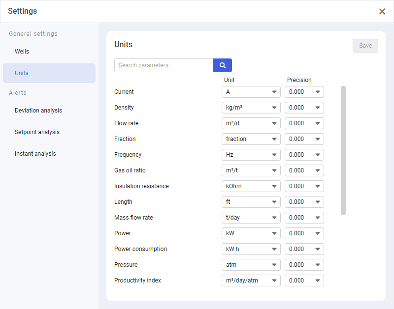
3.1.1.2. Configuring Measurement Units#
In the nv.EBS module, you can select units of measurement and set their display precision, i.e. the number of digits after the decimal point.
To configure measurement units, perform the following actions:
-
At the top of the well management pane, click Settings (
). The Settings window opens. Select image to enlarge
 -
In the left part of the window, click Units. In the right part of the window, a list of well parameters appears.
Note
You can find a parameter by name. To do this, at the top of the list, in the Search field, enter the parameter name or a part of it.
-
To the right of the desired parameter name, in the Unit column, select the desired option.
-
In the Precision column, select an option with the desired number of decimal places.
-
(Optional) To cancel a change of the measurement unit and/or precision, to the right of the modified parameter row, click Reset (
). -
In the upper-right corner of the window, click Save. The Settings window closes, and the changes are applied automatically.