Tutorial: intermittent well design
Tutorial: intermittent well design: Appendix C: Tutorial for Intermittent Well Design Open the nv.design module. For details on navigation in the system, see System Interface.…
Appendix C: Tutorial for Intermittent Well Design#
-
Open the nv.design module. For details on navigation in the system, see System Interface.
-
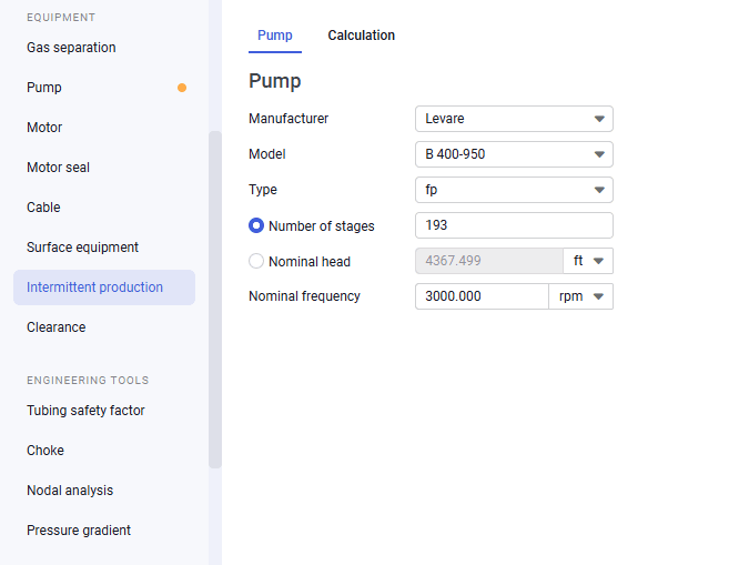
In the left part of the working area, in the list of the module sections, click Intermittent production. To the right of the list, the Pump tab opens.
 Select image to enlarge
 -
On the Pump tab, select a manufacture, model, and type of the pump from the corresponding lists.
Note
If you have already selected a pump in the Pump section, this data is automatically pulled from there (the first pump section only). You can select another pump and/or edit its parameters. To revert the pump selection to its initial model, click the Revert to calculated value (
 ) button that appears to the right of the first three parameter lists.
 -
Select the Number of stages or Nominal head option and enter the corresponding parameter value. The value of the other parameter is calculated automatically.
-
(Optional) In the Nominal frequency field, modify the frequency value. The default value is 3 600 rpm.
-
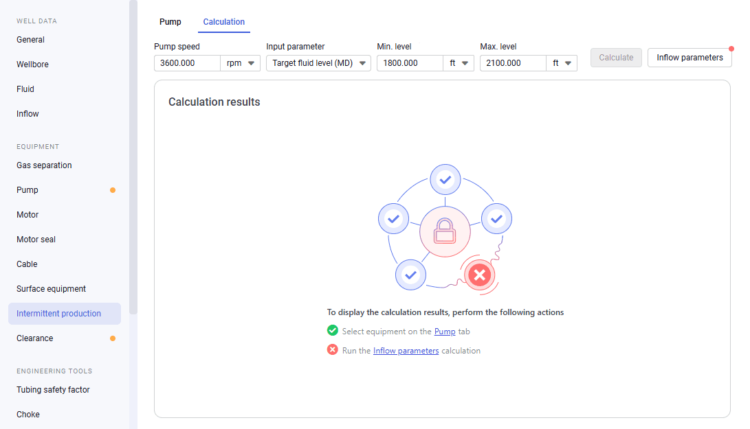
On the Calculation tab, in its upper-right corner, click Inflow parameters and configure initial well production conditions. For details, see Calculating Inflow Parameters.
 Select image to enlarge
 -
(Optional) At the top of the tab, enter the desired value in the Pump speed field. By default, its value is set to 3600 rpm.
-
At the top of the tab, from the Input parameter list, select one of the following options:
-
Target fluid level (MD): Calculation based on the minimum and maximum dynamic levels.
-
Target bottomhole pressure: Calculation based on the accumulation time and bottomhole pressure.
-
Target intake pressure: Calculation based on the minimum and maximum pressures.
-
-
Depending on the calculation method selected at the previous step, to the right of the Input parameter list, enter the corresponding parameter values.
-
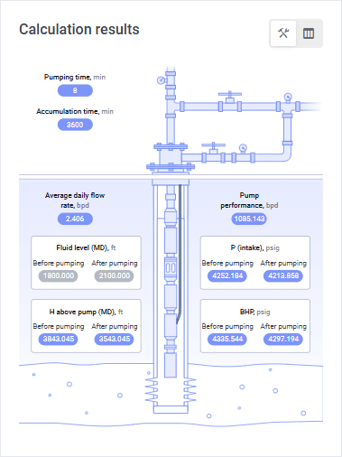
In the upper-right corner of the tab, click Calculate. In the Calculation results pane, on the well structure layout, calculated values appear in the parameter labels. Gray labels correspond to the entered values; blue labels indicate calculated parameters.
 Select image to enlarge
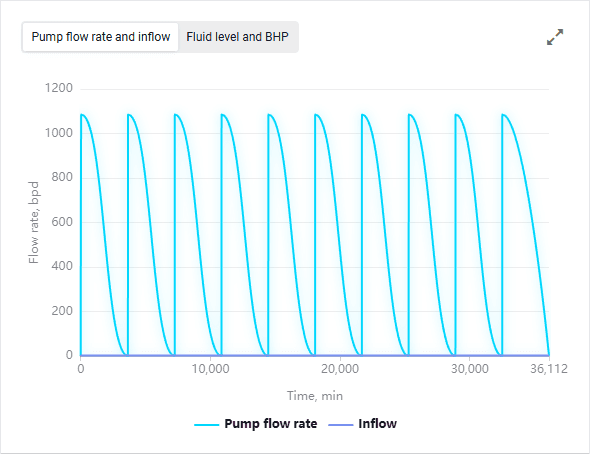
In the right part of the tab, charts with extended calculation results for each of the ten calculated pumping-accumulation cycles are displayed.
 Select image to enlarge
For details on the calculation results, see Calculation.