
Motor selection and configuration
Motor selection and configuration: 5.2.3 Motor The Motor section provides information about the pump motor installed in the well. Note To perform calculations in this section,…
5.2.3 Motor#
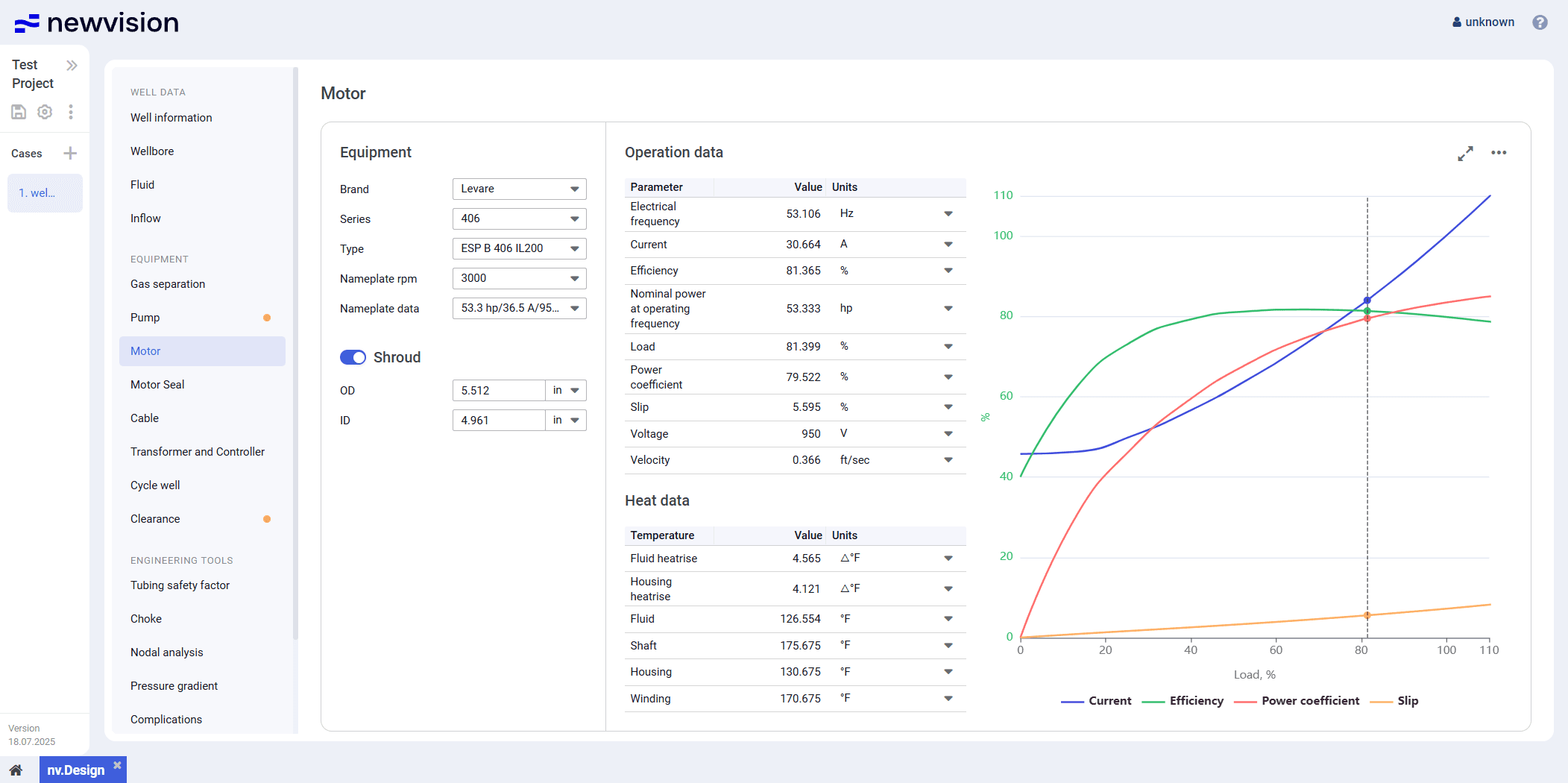
The Motor section provides information about the pump motor installed in the well.
The section consists of the following parts:
- Equipment pane in the left part of the section.
- Operation data and Heat data tables in the central part of the section.
- Visualization pane in the right part of the section.
 Select image to enlarge
Equipment
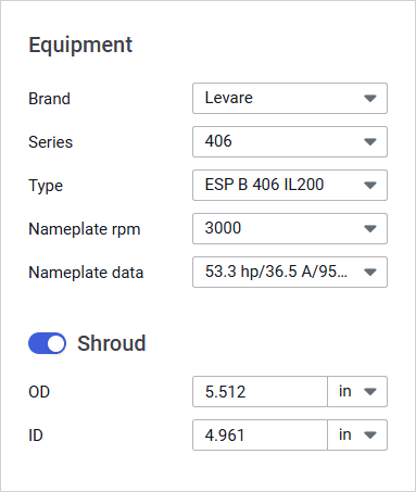
The pane provides controls for the motor selection.
 Select image to enlarge
To select a motor, select the desired options from the parameter lists.
 | Note The nv.design module supports calculations for permanent magnet (PM) motors, high-speed, and low-speed motors (for PCP lift type). |
If a shroud is used, enable the Shroud parameter group using the corresponding toggle.
| Note To enable the Shroud group, all motor parameters must be specified. |
In the Shroud group, you can edit default values of the shroud outer ( OD ) and inner ( ID ) diameters.
If the shroud is not used, the fluid velocity is calculated in the annular space between the casing and the motor housing.
Operation Data and Heat Data
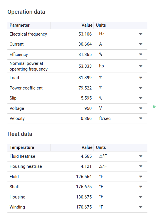
The Operation data and Heat data tables provide calculation results for the selected motor configuration.
 Select image to enlarge
The Electrical frequency parameter corresponds to the rate at which the alternating current changes direction. It determines the rotational speed of the magnetic field in the motor stator and directly affects the shaft’s rotational speed. This value is calculated based on the number of motor poles and the actual rotor speed. In induction motors, the rotor always spins slightly slower than the magnetic field—a phenomenon called slip (the Slip parameter in the table)—which is essential for generating torque.
| Note The Electrical frequency parameter is displayed and must be set by the dispatcher on the controller as a key operating parameter. |
The Velocity parameter and parameters from the Heat data table can be used to select a motor with suitable dimensional specifications and maximum winding temperature.
Visualization Pane
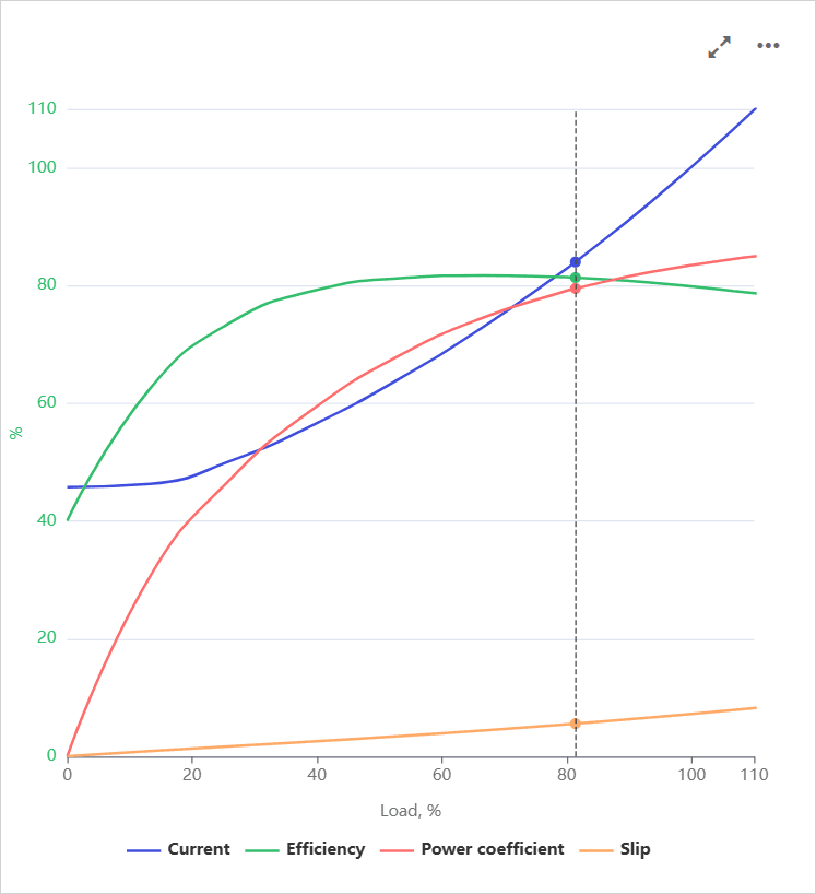
The pane contains a chart that represents the motor performance parameters under varying motor loads (X-axis) along with their percentages compared to nominal values (Y axis).
 Select image to enlarge
On hovering over the chart, a vertical dashed line is displayed. The intersection points of the line with the parameter curves represent the motor operating points. On hovering over these points, a window with information about the exact parameter values at this point is displayed.
To show or hide a parameter on the chart, click the parameter name under it.
You can also expand the pane to full screen or collapse it back to the original size using the Expand (  ) / Collapse (
  ) buttons located in the upper-right corner of the pane.